"System Name" "FVMPE-RS" / "System Version" "2.3.1.163" / Location: NYU Langone Health Science Building, 435 East 30 Street, Room 448, New York, NY 10016
Online signup: https://nyumc.ilab.agilent.com/schedules/350002#/schedule/week7
All new users should read this document. After initial training, please reread this document: FVMPE-RS_Acquiring_images.pdf
High speed, high sensitivity, deep imaging multiphoton microscope
Correct filter sets need to be installed. This involves knowing the colors being imaged and understanding which detectors will be used. Practically, the filters need to be inserted into the system and they will be programmed into the software after startup. We envision that a few users will be trained to do this for their projects (and they will be required to follow the steps for documenting all hardware changes made). Most users will need to schedule ahead with staff. At the beginning of new projects or when characterizing new samples, variations of hardware settings may need to be evaluated before settling on a standard protocol.
Resources The following were provided by Olympus
If you hear beeping from the microscope, IMMEDIATELY Do not hesitate; IMMEDIATELY stop the beeping. Note that in instrument shutdown, you must turn off the detectors in the software before quitting fluoview. |
Instrument startup
All new users should read this document. After initial training, please reread this document: FVMPE-RS_Acquiring_images.pdf
If computer was shut down, power up at any time. If logged in to an account, log out and log in again.
In general, switches on from top of rack to bottom of rack, left to right on each shelf.
Tap switch on small pad for LED for looking at fluorescence by eye.
CBH control box front switch on. Goes into standby mode.
Prior scan control unit for XY stage. Switch is on back right. It needs to be on (and may be left on at all times).
AOM on. (This is a laser.)
AOM on. (This is a laser.)
Touchpad on. Switch is at back right.
Wait for this to boot up with display on screen before proceeding to next step.
DO NOT touch the touchscreen!
Make sure the AOMs have completed initialization before proceeding. You can listen to the microscope to hear when motorized parts stop moving.
Big box at bottom of rack, power switch on front.
Log in to computer.
Make sure microscope hardware has completed initialization. Approx 30 seconds. This is a timed 30 seconds, not what you think feels like half a minute. Or listen to the microscope for when motorized parts stop moving.
FV software.
Select whether to initialize Resonant Scanner &/or Piezo focusing.
Tools > Configuration > IR laser emission
radial buttons for emission status.
Select your favorite Layout. Click Layout button in upper left and select yours.
If using same methods as previous session, open image and resue methods.
Imaging
The biggest problem we have with compromised image quality is saturation and we want to make sure all users learn how to avoid this.
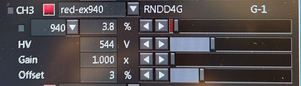
Using the Hi-Lo button to monitor intensity, Offset so background has blue salt-and-pepper look or has no blue. Typically, Offset at 3% works well. If the background is solid blue, you are throwing away data!
Using the Hi-Lo button to monitor intensity and when the contrast range is set full range, bright areas should not be red. Red is saturation. It may damage the GaAsP detectors and saturating bright signal reduces spatial resolution and prevents quantification of intensities.
The "gain" setting is essentially equivalent to boosting the brightness of an image digitially using a function like brightness/contrast, but the gain feature may introduce more noise and irreversable saturation. (Reminder, do not saturate pixels intensities.) If you need to see weak signal directly next to bright signal, adjust the gamma in the LUT window.
Gain should be set at 1 and left there.
The sliders from top to bottom for each channel are as follows:
Top slider is laser intensity. Be careful with this, especially with live samples, to avoid damaging the sample.
HV is the voltage across the detector. This is useful to turn up, but not to the point where there are saturated pixels. This is the useful gain setting to get real increase in signal.
"Gain" is an electronic version of boosting intensity similar to the digital version using LUTs, but is adds noise. It should be clamped at 1. Use LUT instead to change intensity after collecting an image.
Offset at 3% is reasonable. It should be set so that when using HiLo LUT, the background is not solid blue. The background should be completely gra or blue with speckles of black "pepper" throughout. If it is solid blue, this is set wrong. You are losing real data.
People say they need to saturate to see the weak signal. The weak signal is usually captured, but you don't see it because it is outside the rangethat can be seen on the screen. This hidden low signal may be revealed by changing the Look Up Tables (LUTs) after image collection. Saturating the image makes this more difficult or impossible regardless of the "common sense" feeling that saturation is better to see more. (Please contact staff for a demonstration.)
Saving files
Each menu for image collection in FluoView has it's own save path and save names. Make sure you have all the menus populated correctly so you don't lose files.
Any files stored on Desktop or Drive C: may be deleted at any time without warning. DO NOT STORE ANYTHING ON THE DESKTOP OR DRIVE C: The only warning that files may be deleted is the warning you just read.
Where to store files:
Your lab should have a directory on drive D:
You should have a subdirectory in your lab's directory.
If we have a problem with the HD filling up, we will delete files moving roughly from oldest tonewest.
It is your repsonsibility to keep track of your data.
Drive E: is a solid state HD for high speed imaging. Do not store data here. As soon as you are done with imaging, copy your filed to D:.
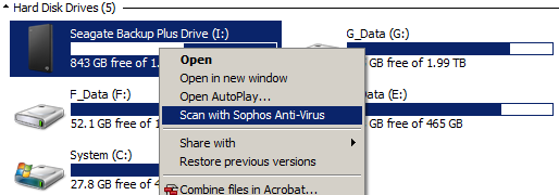
If you are transferring data to an external hard drive or other USB device, BEFORE inserting into the computer, make sure the entire drive was scanned by anti-virus softtware, preferrably the insitution's. Plan ahead.
Filter sets for emitted fluorescence / harmonics
There is a total of four detectors.
Two are GaAsP detectors that are highly sensitive and you have to be careful not to overload them with too much light. They can be permanently damaged.
There are two PMTs that are less sensitive, but a lot more robust.
The filter sets are not on automated filter wheels; they need to be manually loaded.
The filters are paired as blue/green and red/far-red. There is also an option for green/red.
We have mirrors for the following:
You would install the filters to send the weakest signals to the GaAsP detectors. In general, don't send second harmonics to the GaAsP detectors.
Click here to see two example configurations for imaging blue, green, red, and far-red.
Considerations choosing detectors.
The GaAsP detectors are more sensitive, but more sensitive is not always better. They are higher contrast (narrow dynamic range) and can be harmed by excessive bright signal.
The PMTs (photo multiplier tubes) are less sensitive but allow for a wider range of signal.
In general, 2nd harmonics should always be sent to the PMTs because of the wider dynamic range, because 2nd harmonics tend to be brighter, and because you're unlikely to image the 2nd harmonics deep in the tissue.
When setting up channels in the software, each detector may be imaged twice for a total of 8 channels per scan. This is because each channel may be imaged by each laser line in sequence.
There are two lasers. You may excite simultaneously, in rapid sequence line-by-line, or per frame scan.
For instance, you may find it useful to image a red channel twice, once with excitation at 1130 nm and a second time with excitation at 930 nm. This should provide separation of mCherry and RFP respectively.
Why 1130 nm when 1150 to 1200 nm may generate a brighter fluorescent signal especually if also scanning for the far-red channel? If you scan greater than 1130 nm, then second harmonics are visible through the red filter set. To eliminate this, we recommend 1120 to 1130 nm.
Lasers, Insight X3-OL and MaiTai HP DS-OL
There are two lasers. Emission is turned on and turned off from the Tools > Configuration menu.
There is a floating window with controls for the wavelength. At the bottom is a beamsplitter choice of 690/1050 and 690/870. In general, leave it at 690/1050 for use with the MaiTai laser less than 1050 nm and the Insight greater than 1050 nm.
When you change the wavelength of a laser, wait for it to tune and then click the "Start active alignment" button in the fine adjustment pull down menu.
But when using two lasers, regardless whether in the same group or alternating groups, you may still have the following problem:
 and click here for an example with real biology, cells expressing both RFP and GFP.
This is a single 4 um diameter multicolor bead and due to the laser paths at slight tilts, the excitation paths are not in register (not coaligned). To fix this, adjust the Tilt X and Tilt Y. You may want to go to a non-precious area and zoom in at 256 x 256 pixels and scan fast while adjusting. Adjust the Tilt, not the Shift, and this can be done with either or both of the lasers.
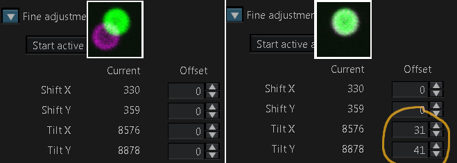
This setting may vary over time and based on room temperature.
Instrument shutdown -- Important to follow so that next user will not have a problem on startup!
Filters
Splitters: 573LP and SDM556R are swapped when reversing blue/green and red/far-red to PMTs or GaAsP detectors.
FV30-SDM-M sends 100% to GaAsP or pulled out 100% to PMTs.
wBlue/Green 460/60 538/40 dichroic 506
narrow BlueGreen 482/35 510/20
FV30-FGR SN7J07173 495-540 DM570 575-645 (According to unimelb)
FV30-FRCY5 a.k.a. F0Cy5 SN7K06455 575-645 DM650 660-750 (According to unimelb)
FV30-FCY (CFP/YFP) SN8B05629 460-500 DM505 520-560 (According to unimelb)
Additional filters:
FF01-550/32-32D
FF02-617/73-32D
FF526-Di01-32x44-FX
Doesn't this block require a 573-Di01-32x44FX ?
In right side of microscope body, a beamsplitter to cut at 680 nm.
Last filter in front of cavity with detectors.
Why? Prevents reflection from laser if tuned low.
Problem: Blocks Cy5 type probes.
Part # BA685 RXD
BA750 RXD
HV Voltage across detector
GAIN digital gain, keep at 1
OFFSET set at approx 3
Set offset for just a few zero pixels blue (using HiLo LUT)
multialkali detectors (PMTs) and GaAsP.
Former have more red senistivity but latter more sensitive at lower-mid wavelengths.
-------------------
Published work using this microscope:
------------------
| Laser service info | |
INSIGHT STDS-OL |
MAI TAI HPDS-OL MARCH 2018 S/N 20479 |