Coverslip Practical issues:
- #1.5 (read below)
- 22 x 22 mm and 18 x 18 mm squares are easier to handle than round coverslips.
- Coverslips are made of different quality glass. If imaging by SIM, recommend high precision coverglass (click here for examples).
- Clean coverslips before use.
- Clean coverslips before imaging. Dry. No Salt crystals. No oil from other microscopes.
- Coverslips mounted on slides immobile.
Mounting media that solidifies should be fully set. Squishy media should have coverslips neatly sealed. No leaking mounting media. No wet nail polish. Do not use nail polish with Prolong (read the instructions).
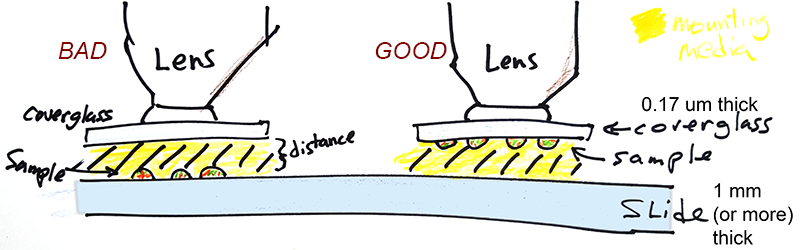
- For highest resolution, samples should be on coverglass, not on the slide.
Most lenses are designed to focus best at the coverslip. Cells on chamber slides imaged through a lot of mounting media will reduce resolution.
- No dapi in mounting media.
- Coverslip in center of slide.
- Always leave at least 3 mm of bare slide at both ends.

- If the sample is mounted in the same center location for all your slides, it will be faster to go from one sample to the next.
|
Coverslips, chambers and working distance.
Most lenses used for biological microscopy are designed to be used with a #1.5 coverslip. Any lens which says 0.17 on the side should be used with a #1.5 coverslip.
Every microscope lens is designed for imaging through a specific type of coverslip, chamber, or at a sample directly. It is important to use the correct coverslip or chamber with the lens you are using to get the best possible image.
"The coverslip thickness is the least expensive optical component and the most likely to be carelessly chosen. It should be 170 +/-5 um in thickness." [Pawley 2018]
A common mistake in biological microscopy is using the wrong coverslip. In general, you should always use a 1.5 coverslip. All the high resolution (a.k.a. high numerical aperture) objective lenses we use are corrected for #1.5 coverslips.
Again, don't use 0, 1, or 2. Use 1.5. If you have #2 coverslips, just throw them out and buy #1.5 instead. Really. #2 coverslips are too thick to focus through.
For TIRF (Total Internal Reflectance Microscopy) the material must be glass and the mounting media must be aqueous.
For laser based autofocus, the material must be glass and the mounting media must be aqueous.
I like 18 mm or 22 mm square coverslips because they are easy to handle. Unless you are using extremely small amounts of precious reagents, I advise staying away from the tiny round coverslips, but this merely a matter of your comfort; as long as they are #1.5 the image quality will be the same.
This is an example of imaging in a chamber with a thich plastic or glass bottom. It works with longer working distance air lenses only.
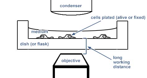
Many LWD lenses have an adjustable collar to optimize the imaging quality for chambers composed of different thicknesses and materials.
Higher resolution imaging must be performed through a number 1.5 coverslip. For optimal imaging, the cells or tissue should be very flat and sandwiched between a standard glass slide and the coverslip as illustrated. For oil immersion objectives, the coverslip must be fixed in place either by a mounting medium that polymerizes or by nail polish or glue around the edges.
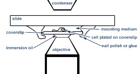
This method of sample preparation is useful only for fixed and stained material or for some limited applications where the space between the coverslip and slide may be an open chamber. For instance, some people use a small diamond drill bit to make holes in the slide which may be used for fluid exchange.
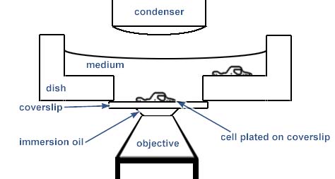
An easier method for live cell imaging is to grow the cells in special chambers which have a coverslip at the bottom:
Other examples are:
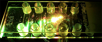
Most microscope stages hold the sample in placed with thin metal under the long ends of the sample. For instance, wells that extend all the way to the ends may not be accessible to the lens. Also, tabs on chambers may need to be cut off to allow the chambe to sit in the recessed stage. The Nunc / LabTek II chambers have both these problems. In the 8 well system pictured, only the middle 4 wells may be used and the bottom tab needs to be clipped or shaved off.

more pics at https://www.flickr.com/photos/mcammer/8553907257/ and https://www.flickr.com/photos/mcammer/8553907715/
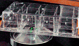
This chamber system by Ibidi allows for all 8 wells to be accessed.
Also, different heated inserts may have their own required geometries.
The following links are example products which have the correct #1.5 coverslip bottoms. In addition, each microsope may have it's own additional requirements for geonetries. (Dislclaimers: we have no commerical interest in any of these and there may be other solutions not listed here.)
Remember, #1.5 coverglass.
MatTek glass bottom dishes have been our workhorse solution for more than 20 years. Make sure you purchase #1.5.
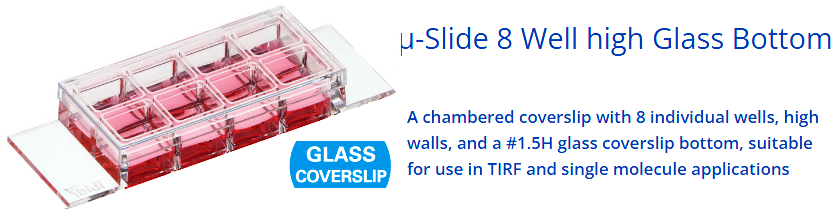
Ibidi sells a wide variety of chamber geometries for microscopy.
Where there are options for the type of glass, choose #1.5
(170 um +/- 5um).
If you choose polymer
coverslips, be aware these will not work with TIRF, SIM, or autofocus. They may have reduced resolution with confocal and widefield, but are acceptable for most applications.
Chambered Coverglass System 1.5 Borosilicate Glass - ThermoFisher N.b. The wells at the end may not be fully accessible to the microscope lens. Also, you have to cut off the plastic tab.
Nunc® Lab-Tek® II chambered coverglass, 8 wells, polystyrene chambers, 1.5 borosilicate coverglass, 0.7 cm2/well N.b. The wells at the end may not be fully accessible to the microscope lens, so keep them empty.. https://assets.thermofisher.com/TFS-Assets/LCD/Specification-Sheets/Nunc-Glass-Bottom-Dish-spec-sheet.pdf https://www.thermofisher.com/order/catalog/product/150680
Bioptechs has a number of solutions (but have to be careful of metal rings that block lens access).
Fisher now (as of 2017) sells dishes & chambers by Greiner such as Bio-One CELLview™ Sterile Cell Culture Dishes With Glass Bottom and Cellview slides which really shouldn't be named "slide" since they have coverglass bottoms.
More
pictures here.
(last updated 20170407)
The following products were added to this list in 2022.
https://www.cellvis.com/_29-mm--glass-bottom-dish-with-14-mm-micro-well-number-1.5-cover-glass_/product_detail.php?product_id=21
https://www.cellvis.com/_29-mm-glass-bottom-dish-with-20-mm-micro-well-number-1.5-cover-glass_/product_detail.php?product_id=25
https://www.cellvis.com/_29-mm-glass-bottom-dish-with-20-mm-micro-well-number-1.5-high-performance-cover-glass_/product_detail.php?product_id=71
Plastic coverslips do not work with TIRF and autofocus:
https://www.cellvis.com/_29-mm-dish-with-20-mm-micro-well-and-number-1.5-glass-like-polymer-coverslip-tissue-culture-treated-for-better-cell-attachment-than-cover-glass_/product_detail.php?product_id=72
For small volumes, these tubes work. However, note that the glass wall is only 0.14 mm thick whereas the ideal thickness would be 0.175 mm.
https://www.vitrocom.com/product/3520/
Please note that in the chambers, the bottoms are #1.5 coverslips, not slides. A common mistake is using chambered slides rather than chambered coverslips.
Some chambered slides may have the chambers removed and a coverglass may be put over the chambers. The problem with this is that the microscope has to image through thick mounting media which often has mismatched refractive index. Most lenses are designed to image at the coverslip, not far from the coverslip. Therefore, resolution may be degraded or the distance may be too great to focus. High resolution is compromised, but sometimes acceptable images may be attained, just not ideal ones.
Mounting cells grown on filters
It's a tough balance between squishing the cells and having too much space.
The filter must be sandwiched bewteen the slide and the coverslip with the cells on the coverslip side. One way to play this safe is to sandwich the filter between two 22 X 60 mm coverslips so that the cells may be imaged from either side with a high numerical aperture objective.
The filter needs to be squished enough to lie flat and to present the cells near the coverslip but not be squished so much that the cells are too flat.
Other Problems to Avoid
Plastic slides should be avoided. Even with aqueous mounting media, plastic slides tend to curve. Plastic slides warp with non-aqueous mounting media as the media is absorbed by the slide. It is very common to have focus drift problems with plastic slides. If you do have this problem, put a glass slide against the bottom of the plastic slide to provide a rigid backing.
Plastic slides and dishes cannot be used with polarized light techniques. Some plastic slides cannot be used with phase contrast.
An alternative is to grow cells on coverslips coated with a protein that the cells like to adhere to, such as polylysine, collagen or firbronectin or maybe a synthetic compound such as PDMS. Resolution is better with most of the lenses we have when sample is directly on coverslip.
Do Not Squish Samples When Mounting. Especially for confocal microscopy, where three dimensional morphology should be preserved, it is important to not squeeze the sample when mounting it.
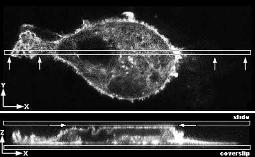
Top image: Confocal microcopy single optical section through the center of a mammalian cancer cell stained for f-actin. The box shows where the cell is resampled in the Z axis. The arrows show the view in the bottom image.
Bottom image: View in Z axis of narrow slice marked above in a Z series. The cell is growing on and adherent to the coverslip. Due to being mounted too tightly, the slide is pressing on the top of the cell making it flat and forcing some of the membrane at the apical surface to fold to fit against a flat surface. |

A: Diagram of the cell flattened at the top.
B: Diagram of the cell as it should appear in its natural unsquished state. |
Exceptions to the #1.5 rule
#0 or #1 coverslips, because they are thinner than #1.5, may provide more working distance necessary for very thick specimens such as imaging deep into C. elegans with a 40X N.A. 1.4 lens. You do have to be careful not to crack the coverslip as they are more fragile and understand that there may be a tradeoff of loss of spatial resolution, especially in the Z axis. Also, precise Z depth measurments may need to be adjusted for shortened light path through the glass, but for simple imaging this may not be relevant.
For materials science, we've found that tubes with a flat surface and a wall thickness of 0.14 mm work well.

These can be attached to a slide for support.
Multiphoton microscopy, especially with a water immersion adjustable collar lens, may tolerate a wide range of coverslip thicknesses too.
Link to poly-L-lysine coating.
Do not put samples too close to the end of the slide.
If the samples (what you want to image) are too close to the end of the slide, then the lens will crash into the stage. This happens with both upright and inverted microscopes.
If the lens gets too close to the stage, it will crash into the stage, and this would damage the lens &/or bend the stage.
Therefore, samples cannot be imaged if they are too close to the end of the slide. Anything you need to image must be more the 5 mm from the end of the slide.
Do not move the lens closer to the edge of the sample than pictured here.

<--Back
This web page was modified from http://cammer.net/historical/aif/instructions/coverslips/coverslips.htm
comments, questions, suggestions: Michael.Cammer@med.nyu.edu
The author of this webpage has no financial interest in any of the products mentioned on this page.