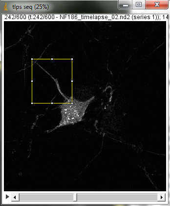
20180118 Nikon W1 spinning disk demo with cultured cells system. In this sample, GFP tagging structures that move in cells. Cells plated on #1.5 coverslip. Unpublished so not more biological info given at this time.
Timepoints are 0.20 sec per frame. Our gut feeling is that this is more sensitive than the iSIM system we tried 2 years ago (http://microscopynotes.com/users/VT-iSIMdemo-201602/neurons/index.html), but we have been told that in the intervening two years, better alignment procedures and more judicious selection of lens may be better than this. Without comparing same samples and taking laser power at sample measurements, hard to compare. Likely both could crack this biology imaging problem.
Top: overview of entire field; bottom: region of interest at original spatial scale
From metadata:
Apo 60x Oil ý S DIC N20Rý  Numerical Aperture = 1.4
Camera Name = Flash4.0, SN:300784
wszFormatDesc = 12-bit - No Binning (100.0 FPS)
Width:  143.2167 microns (1322)
Height:  149.5000 microns (1380)
Voxel size: 0.1083x0.1083x1 micron^3
Frame interval: 0.20001 sec
sSpecSettings = Exposure: 200 ms
final timestamp:  timestamp #600 = 120.17690608629677
original data size 16 bits 2 GB
How this was done:
Float the stack (used macro in Useful Collection on webpage-- optional step)
Maximum projection
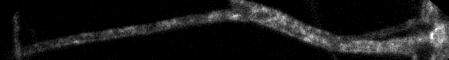
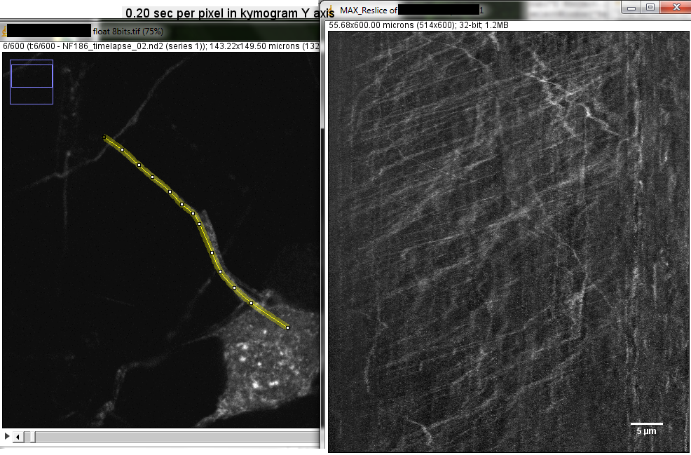
Segmented or freehand line over path of interest in macx projection
On stack, ctrl-shift-e or Edit > Restore Selection
Edit > Selection... > Straighten run("Straighten...", "title=[tlps seq-1] line=17 process");
Line width in pixels wider than the structure, such as 11, 15, 21...
Process Entire Stack
backslash or Image > Stacks > Reslice
Top, interpolation off run("Reslice [/]...", "output=1.000 start=Top avoid");
If you already have a FFT mask, otherwise need to make one
Process > FFT > Custom Filter...
do entire stack
Image > Stacks > Z Project... maximum method run("Z Project...", "projection=[Max Intensity]");
How to make FFT mask:
Immediately following the Straighten command, maximum pixel project.
run("FFT");
cut the horizontal line at the center careful to preserve the center brightest point
In the example below, also cut another pattern in the image.
renamed "MASK" for convenience.
Also see http://microscopynotes.com/imagej/fft/index.html
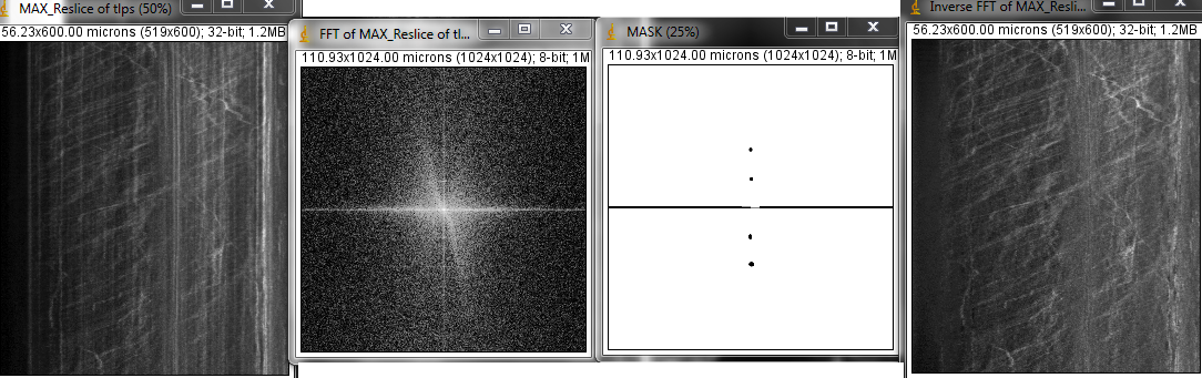
N.b. that there are so many parallel tracks at the same speed that they show up in the power spectrum.
Example macro:
var linewidth =19;

macro "make kymogram" {
  run("Grays");   // OPTIONAL
  run("Straighten...", "title=[MAYBE REPLACE WITH getTitle] line="+linewidth+" process");
  tempimage1 = getImageID;
  run("Reslice [/]...", "output=1.000 start=Top avoid");
  tempimage2 = getImageID;
  // THE FFT DOES NOT WORK ON THE ENTIRE STACK THE FIRST TIME THIS IS RUN
  // Code to make mask could replace the saved image.
  run("Custom Filter...", "filter=[FFT-MASK.png] process");
  run("Z Project...", "projection=[Max Intensity]");
  resetMinAndMax();
  selectImage(tempimage2);
  close();
  selectImage(tempimage1);
  close();
}
Click here for the mask file used.